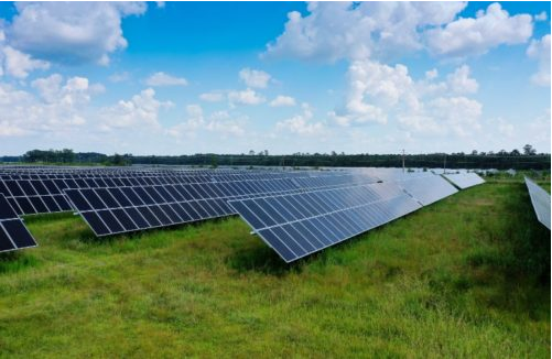
As the solar industry drives toward large-format modules FTC Solar unveiled the Voyager+, a new two-in-portrait-design solar tracker that aims to optimize energy capture while reducing the manpower and equipment needed for installation.
FTC Solar reported the Voyager uses 46% fewer foundations than comparable one-in-portrait systems. FTC has more than 1 GW of planned or installed solar capacity that using the Voyager.
“As the solar industry moves toward large-format modules of 550 W or higher, traditional one module in portrait tracking systems have difficulty supporting these new large ‘sails’ while two-in-portrait designs have already had this experience of scaling to larger surface areas. Because the static and dynamic wind loads are much greater on the structures, with these large formats, there is an ongoing need for improved tracking designs,” said Nagendra Cherukupalli, CTO of FTC Solar. “To answer this call, our team developed Voyager+ to tap into the benefits of 2P designs with proper management of wind loads and the seamless integration of large, complex solar modules – resulting in a zero-stow design.”
FTC Solar conducted extensive wind tunnel testing and modeling to develop a unique dampener design to mitigate the effects from wind that may cause vortex shedding and torsional galloping that is validated by RWDI Tunnel Testing.
FTC Solar collaborated with RWDI and Engineered Power Solutions (EPS) on data analysis and wind tunnel testing to independently validate the product’s structural stability, handling speeds up to 120 mph.
FTC Solar first conducted code-based methods used commonly in engineering to understand static wind forces based on design parameters at the site, wind speed, exposure and similar factors. Initial sensor-based testing was performed with models of the Voyager 2P system to measure static wind loads and how they affected the structures.
“Utilizing our baseline understanding from the RWDI model test, FTC developed a highly damped system design,” said Matthew Gilliss, CEO and president of EPS. “By undergoing these tests, their engineering team developed an understanding of common system flaws in design and what preventive measures were necessary to eliminate the risk of aeroelastic instability.”


